You will need a multimeter with diode mode ( most have it )
Buy this DMM from Ebay UK here
this is a bargain multimeter same as mine they are excellent .
The rectifier regulator converts AC output from the alternator into DC 14 volts to charge the battery
. 14V is needed to charge the battery and DC is needed to operate the Coils and ECU without this the bike will not run .
The Rectifier is a package of diodes that only lets the current through one way and block it from flowing the opposite direction .
We need to test each of these diodes in each direction and at the same time make sure they are not shorted .
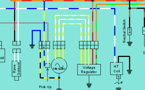
Three yellows 2 reds one blue
3 at bottom are yellow making it easy to id them
Here is the wires 3 yellows from alternator
are incoming AC lives the 2 outgoing wires red and
red/green should be regulated and rectified to 14v~15vDC
The blue wire is the ground reference for rectifier and can be ignored for this test .
So basically we test between the red wire and then the red/green
to all yellow wires in both directions or polarities with multimeter leads
so to start with lets set the Multimeter to diode mode seeing as we are testing diodes we are looking for a voltage drop of 0.5~6 one way and nothing or OL in the other direction .
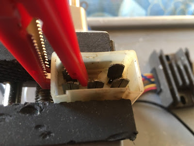
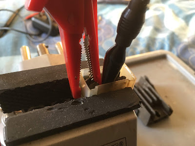
here i attach the red positive lead to the upper left wire in terminal
block red and green , i then test between this and all the yellow wires with my black lead .
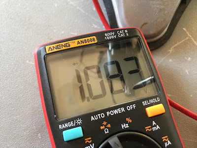
here i get a diode voltage drop of 1.083 volts i was expecting
0.6 so a bit over could be sign of a failing rectifier .
so now i jump to middle bottom yellow terminal
1.071 volt drop so its similar to above but still over expected 0.6v.
now move black negative lead the last yellow wire
and i get 1.083 so a bit more than i expected but at the same time
all readings are similar so i am not too concerned now
Now i move the red positive leads over to the next upper terminal red wire
and test between this and the three yellow bottom terminals again .
this time i get OL on all readings showing these diodes are functioning ok
this side .
first yellow
middle yellow
last yellow .
Now we have to do all the same above but in reverse ie with the negative black lead from multimeter connected to to the upper red and red green wires and touch the red positive multimeter lead to the yellow alternator wires .
as you see below attach black negative lead from multimeter to the top left terminal red/green wire and test between it and the yellow alternator wires with the red positive lead .
Now the middle yellow
Now swap the negative lead of multimeter to the right side upper terminal or red wire and test with positive to the 3 yellows , you know drill by now.
all these are 0.552 which id say is more normal for these rectifiers .
Results as you see you should get OL one way and reading of 0.6v drop the other the fact this read 1.07v drop on some makes me think this is on its way out but to be honest this is the first one i have tested so do not have enough experience to condemn it plus this is from a running bike .
If at any time you had a short circuit you would get this reading in diode mode
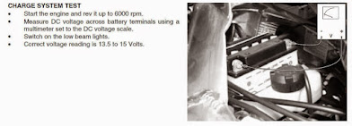
to test the regulator is putting out the correct voltage just test at the battery , this test tells you the alternator , charging circuit and regulator inside rectifier is functioning good .
If you do need to buy a new Regulator rectifier for your Aprilia RS


